In machine vision a basic requirement is to separate color components in different images. This could be for example the separation of RGB into it's components, but as well the separation of HSL or XYZ etc. In the following, some examples for color separation are shown. All examples use a RGB area scan camera for input. Of course, the examples can be applied to line scan cameras as well. Moreover, an antecedent Bayer De-Mosaicing or a color space conversion is likely and can be easily added to the examples.
The examples assume that the color separation is required for post processing on the host PC. Therefore, the examples focus on color separated DMA transfers. If you need a processing on color separated data in the FPGA, the examples can also be applied to your requirements.
Several examples are shown. The result of all examples is the same. However, the implementations are completely different and all have their pros and cons. You will need to select the example which fits best to your requirements. The following table lists all examples and some of the properties.
| Example Name | Latency | DRAM | No. of Block RAM | DMA Output |
|---|---|---|---|---|
| Three DMAs | No additional latency | 1 DRAM buffer | low | 3 DMA. One for each color component. |
| Sequential with 3 buffers | Latency minimized to theoretical minimum. | 3 DRAM buffers | low | 1 DMA. Sequential color component output. |
| Sequential with MultiROI Buffer | 1 frame latency and bandwidth limitation. | 1 DRAM buffer | normal | 1 DMA. Sequential color component output. |
| Sequential with pre-sorted MultiROI Buffer | 1 frame latency | 1 DRAM buffer | high | 1 DMA. Sequential color component output. |
| Sequential with advanced buffer usage | 1 frame latency | 1 DRAM buffer | low | 1 DMA. Sequential color component output. |
Table 20. Overview of Color Separation Examples
A full description of the properties shown in the previous table as well as full descriptions of the different methods are outlined in the following sections.
| Brief Description | |
|---|---|
|
File: \examples\Processing\Color\ColorPlaneSeparation\ColorPlaneSeparation_Option1_ThreeDMA.va |
 |
|
Default Platform: mE5-MA-VCL |
|
|
Short Description RGB color plane separation examples. The components are split into three DMA output channels. |
|
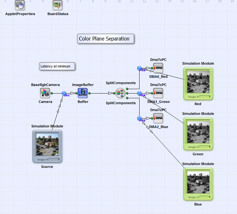
This example is very simple. The input RGB image is buffered and after, the color planes are split into three output links. These three links are transfered to the PC using three DmaToPC operators. An advantage of this solution is, that you have a minimized latency. The image is not buffered in the frame grabber. Operator ImageBuffer will only delay the image by one line if the host PC is fast enough. No additional delay is generated. Another advantage is that only one DRAM operator is required.
A disadvantage of the implementation is that three DMA output operators are required. These operators consume many FPGA logic resources of the frame grabber. If you do not require such a minimized latency, you should consider one of the solution presented in the following chapters.
| Brief Description | |
|---|---|
|
File: \examples\Processing\Color\ColorPlaneSeparation\ColorPlaneSeparation_Option2_ThreeBuffersOneDMA.va |
 |
|
Default Platform: mE5-MA-VCL |
|
|
Short Description RGB color plane separation example. The components are split and buffered in three frame grabber buffers. After that, the color planes are sequentially output using one DMA channel. |
|
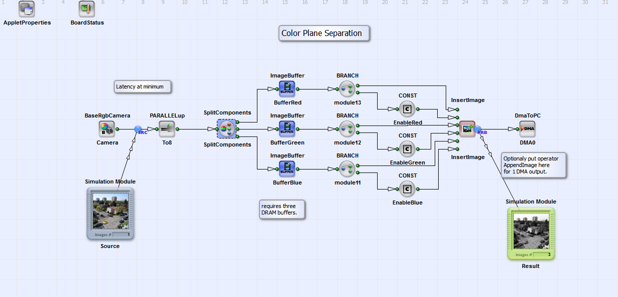
In this solution for RGB color plane separation, the color planes are output in sequential order over DMA channel. This is done by splitting the RGB input into its components and buffering the colors separately in three ImageBuffer modules. Using operator InsertImage, the color planes are read one after each other from the ImageBuffers.
In this example, it is important to increase the parallelism before writing the data into the ImageBuffer. Otherwise you will get a bottleneck after the InsertImage module.
The advantage of this approach is that you will only need one DMA channel which reduces the required resources. Also, the latency is at its theoretic minimum for sequential output. The DMA transfer for the red channel immediately starts without delay. A drawback of this solution is that three frame grabber memory operators are required. As they are limited this solution is only useful if not more of these buffers are required.
| Brief Description | |
|---|---|
|
File: \examples\Processing\Color\ColorPlaneSeparation\ColorPlaneSeparation_Option3_SequentialMultiROI.va |
 |
|
Default Platform: mE5-MA-VCL |
|
|
Short Description RGB color plane separation example. A sequential DMA output of the three RGB color planes is performed. The sequence is generated by ImageBufferMultiRoI. This solution is not good as it limits the bandwidth. See the next example, for an optimized solution. |
|
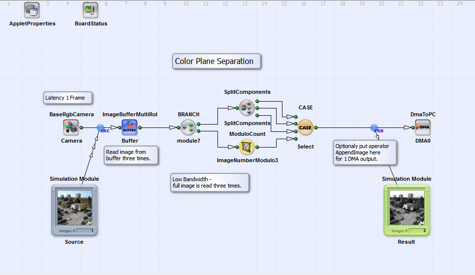
This solution is an intermediate step between the previous and the next example. Because of bandwidth limitations, it is not advised to implement this solution. However, it explains in a simple way on how to get the same output as the previous example with requiring only one frame grabber RAM. To sequentialize the image, we use operator ImageBufferMultiRoI. In this operator, we simply read the same image three times. After, we select the red component for the first image, the green for the second image and the blue for the third image. This can be easily done with the ModuloCount and the CASE operators. The ModuloCount is parameterized to count frame numbers modulo 3 i.e. {0, 1, 2, 0, 1, 2, ...}.
As mentioned, this solution is not the optimum as it reduces the bandwidth. The reason is that we read the same input image three time, but using only one of the three components. Thus in every read cycle, we discard two third of the the data. The next example will show a similar solution which overcomes this limitation.
| Brief Description | |
|---|---|
|
File: \examples\Processing\Color\ColorPlaneSeparation\ColorPlaneSeparation_Option4_SequentialPreSortMultiROI.va |
 |
|
Default Platform: mE5-MA-VCL |
|
|
Short Description RGB color plane separation example. A sequential DMA output of the three RGB color planes is performed. The sequence is generated by ImageBufferMultiRoI. An additional pre-sorting optimizes the bandwidth and solves the problem presented in the previous example. |
|
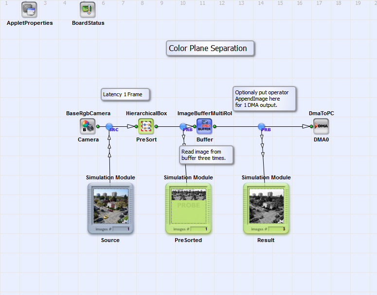
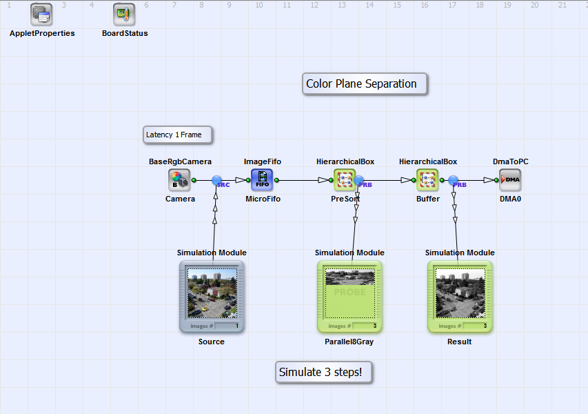
This example is similar to the previous example. In contrast, we do not have a bandwidth limitation in this case. The idea is the same. By use of operator ImageBufferMultiRoI, we sequentialize the three color components. In contrast to the previous example, we do not separate the colors after the buffer. Instead we separate the colors before writing them to the buffer. This is done in the the HierarchicalBox PreSort which content is shown in the following figure.
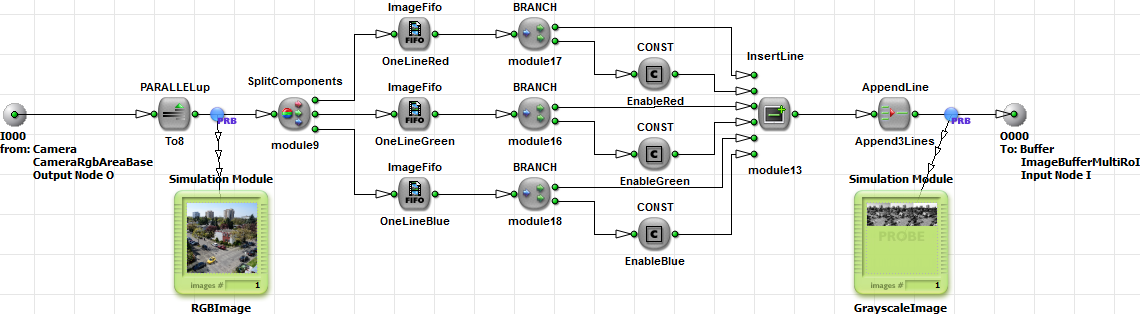
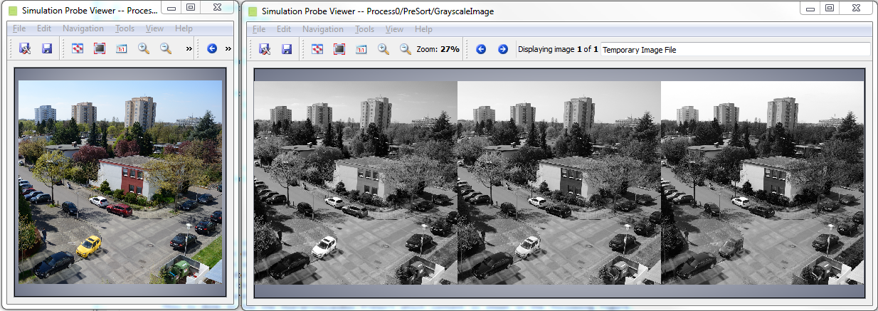
The idea of this approach is to separate the color components before writing them into the buffer. This is done for every image line. Thus we split the color components into three links. These resulting grayscale links now contain the image lines of the input images. Next, the lines are multiplexed and appended. The result is that we have thre grayscale images in one large image. The red component is on the left, the green in the middle and the blue on the right. Have a look at the simulation results in the next figure to understand the implementation.
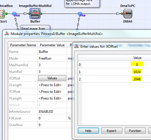
In the ImageBufferMultiRoI, we now have to read the left part first. After that the middle part and finally the right part. Thus, we need to set a different XOffset for each ROI as shown in the following.
When using, do not forget to increase the parallelism before separating the components as shown in the example. This is required to avoid a bottleneck after the InsertLine module. We need at least a three times higher parallelism than the input as we transfer grayscale 8 bit image and not 24 bit RGB images anymore.
This solution does require only one DRAM operator and does not limit the bandwidth. This is an optimized solution. However, some block RAM is required to buffer the separated component lines in the FIFOs. For small images, this should not cause a problem. However, if you have large image widths such as 16384 pixel per line, many block RAM is required. This last drawback is solved with the next example.
| Brief Description | |
|---|---|
|
File: \examples\Processing\Color\ColorPlaneSeparation\ColorPlaneSeparation_Option5_SequentialAdvanced.va |
 |
|
Default Platform: mE5-MA-VCL |
|
|
Short Description Example on separation of color planes. The RGB input is split into its component and sequentially output via one DMA channel. The splitting if performed by collecting same components in parallel words and reading with FrameBufferRandomRead. |
|
This is the most advanced example for color plane separation in VisualApplets. It is focused on a minimum resource usage and maximum bandwidth. The previous example used a pre-sorting to separate the color components so that we could individually read them from the buffer. However, some block RAM is required for the FIFOs in the pre-sorting. In this approach, we use a pre-sorting, too. In contrast, we collect 8 successive pixels of each color component only before switching to the next component. In the previous example, we collected a full line of one component before switching to the next line. This modification results in that we do not need FIFOs anymore. However, the ImageBufferMultiRoI cannot be used in this case. Instead, we have to use a FrameBufferRandomRead.
The pre-sorting is simple. First, we increase the parallelism to eight. Next, the components are split. This results in three links with parallel eight each. MergeParallel will now put the eight pixel of the components in a sequence. We will therefore get a sequence: R0 to R7, G0 to G7, B0 to B7, R8 to R15, G8 to G15, B8 to B15, ...
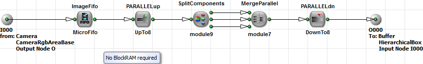
Figure 266. Pre-Sorting for Color Separation by collecting eight successive pixel of the same component.
The FIFO at the input is required because of PARALLELdn from 16 to 8. This FIFO is required only to avoid a DRC level 2 error. In fact, it will not need to buffer data, so that we set it to a very small size of 2 pixel only.
After we have pre-sorted the pixel, they are buffered in a FrameBufferRandomRead operator. This operator has read row and column address inputs and allows to randomly read the data.
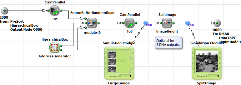
The operator can only be used with a parallelism of one. Therefore, we use CastParallel to cast from parallelism 8 at 8 bit per pixel to parallelism 1 at 64 bit per pixel. That's why we collected eight successive pixel in the previous step.
To separate the color components we have to increase the addresses by two to jump over the unwanted colors. For the red component, the read addresses will therefore be: RColA(0) = 0, RColA(1) = 2, RColA(2) = 5, ... For the green component, the read addresses will be: RColA(0) = 1, RColA(1) = 3, RColA(2) = 6, ... Hierarchical box AdressGenerator does generate these read addresses. A CreateBlankImage operator defines the required image dimension. As we previously used CastParallel from 8 to 1, we have to use an image width divided by 8.
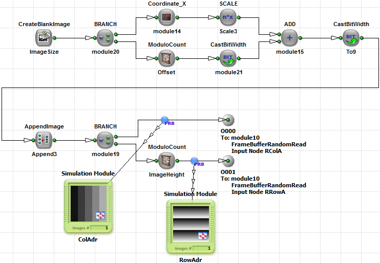
The column address is simply generated with scaling the Coordinate_X output by 3. Depending on the current component, we add 0, 1 or 2 as an offset to the values.
By use of AppendImage, the three address images are merged into one larger image. The row address is simply generated with a counter between 0 and the image height. In this case, we use a ModuloCount operator for this task. The addresses can now be fed into the FrameBufferRandomRead operator. Do not forget to use a parallelism two at the CreatBlankImage output to maximize the performance of FrameBufferRandomRead.
After the buffer, we obtain a large image where the first lines include the red image, after the image contains the green image and finally the blue. To split this large image into three separated DMA outputs, we use SplitImage and set the image height.
The easiest way to understand the implementation is by looking at the intermediate results step by step. Note that you will need to simulate three steps for one result image. That's because 3 images have to be generated by operator CreateBlankImage.
This solution is resource optimized, as only few block RAM resources are required. Moreover, the FPGA logic resources are efficiently used. The address generation only requires few resources.
